Tutorials

08 Oct 2020 Posted by: Comments: 0 In: tutorial, Unity

Often when we have to import a lot of assets into our project, Editor processing time to import them could be a real pain. Being able to see which asset category takes the longest to import can help you in:

  • Know where to direct your optimization efforts
  • Speed up your import times
  • Speed up platform switch times
  • Improve the performance of your Continuous Integration Pipeline if you’re doing clean nightly builds

There are already Asset store plugins that help you to inspect your Editor import timing, but Unity recently released a free Editor parser. You can download it here: https://github.com/Unity-Javier/SimpleEditorLogParser

To use it, you should import a bunch of assets into your project (textures, audio, scripts, whatever you like) and then make a copy of your Editor.log file, that you can find in C:\Users\username\AppData\Local\Unity\Editor\Editor.log. Paste it in a folder (I’ll use C:\Projects\Game01\). Now let’s parse it with Unity’s SimpleEditorLogParser:

  1. Download the zip file from Github
  2. Open the .sln project with VS2019
  3. If you’re prompted with a warning saying that VS needs some extra module to be installed in order to open this project, do it (this will open VSInstaller automatically)
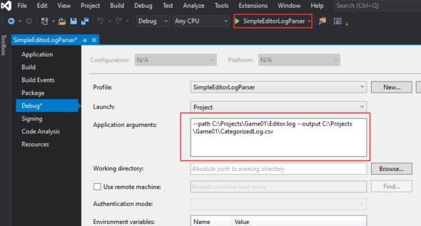
  4. Go to Debug command line settings:
  5. add these arguments:
    –path C:\Projects\Game01\Editor.log –output \CategorizedLog.csv (change the path with the folder where is the copy of your Editor.log)
  6.  Save and Run the project: in the same folder, a cvs file should appear:
  7. I suggest at this time to upload this cvs into your google drive and open it as Google sheet file
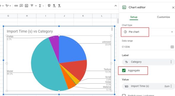
  8. Select both Category and Import columns, and then insert a Chart
  9. Click on the created graph, and inside ChartEditor options select Aggregate and PieChart type. And there we go! We have our ImportTime vs Category Pie chart, ready to give use at a glance what we can do to improve import asset times!
 

24 Jul 2019 Posted by: Comments: 0 In: tutorial

In the previous tutorial, we installed antilatency software to test the tracker for a Desktop app. In this tutorial, we’ll setup a Unity project for the OculusGo, and use AntilatencySDK to test 6DOF on our OculusGo HDM. Let’s start!

Unity project setup

We already downloaded Unity with its Android Build Support.

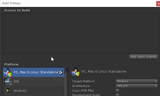
  1. Switch Build Platform to Android in Build settings panel:
  2. Go to the AssetStore and download and import OculusIntegration. It’s free, and it is a collection of modules and scripts that allow a better integration with Oculus SDK inside Unity. This asset store module is mandatory, if you want to use Antilatency VR sample project without problems.
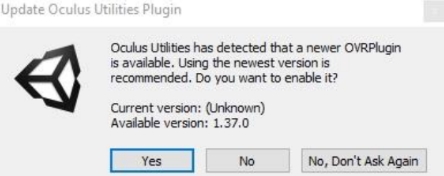
  3. Sometimes (depending on your Unity version) the last step could cause a Unity crash. Don’t worry: restart Unity Hub and reopen the project. If at start a newer version of the plugin is detected, click Yes to update, then Restart again.
     
  4. Now its time to setup project settings for your OculusGo. If you want to develop for VR, you have to take into account a lot of performance issues that could arise, and to know which settings are appropriate for the project, a very good start is to read this post in the official Oculus developer blog. Follow the entire post suggestions, with only one exception: I suggest you to leave the ScriptingBackend option to Mono, to avoid long build times.
  5. Install ADB. Android Debug Bridge is the main tool used to communicate with an Andorid device for debugging. Download platform-tools_r29.0.1-windows.zip from the Android developer website, and unzip the file content in C:\ADB (this directory path is not mandatory, it is only a suggestion). To test it, from command prompt, write: C:\ADB\adb help, and it should reply with the adb help info.
  6. Install ADB OculusGo Driver. Download oculus-go-adb-driver-2.0.zip from the Oculus developer website, unzip the file, right-click on the .inf file and select install.
  7. Set your OculusGo to Developer mode. Go to the Oculus App on your mobile phone and click on your OculusGo. Then click Settings and DeveloperMode: switch it to On.
  8. Using adb from the command prompt, it is possible to connect and communicate with an Android device. Connect your OculusGo via USB to your PC.
  9. From the command prompt, type: adb devices. If it is the first time you run this command, adb should advice you that your OculusGo is connected to your PC, but it is unauthorized. Something like this:

    If your device is not listed:

    • you don’t have the correct USB driver
    • try another USB cable and/or USB port
  10. You have to trust your PC from within your OculusGo. Put your headset on. You should see something like:
  11. Click Allow and then Ok
  12. Now back to the Command prompt: type adb devices again. Now you should see device instead of unauthorized along your device ID
  13. So far so good. Now you are able to install Android builds on your OculusGo. Every time you have to install an .apk build into your Oculus, you should:
    1. Connect your OculusGo to the PC
    2. type adb devices and check that it is connected
    3. type adb install -r C:\<pathToYourApkFile>\ApkFileName.apk (we use the -r option because if you need to reinstall it again, this option will overwrite the existing one)

Antilatency VR project import

  1. Go to your downloaded AntilatencySDK folder: in the previous tutorial we already imported AntilatencyIntegration.unitypackage in our Unity project. If you didn’t, do it now. Moreover, we need to import AntilatencyIntegrationOculusExtension.unitypackage.
  2. Once you imported both unitypackages, you’re almost ready to go!
  3. Open Assets/Antilatency/Integration.Oculus/Samples/AltOculusSample and build the project, including only this scene. Save the .apk file into a /Build folder outside the Asset folder. Name it AltOculusSample.apk, for example.
  4. At the end of the process, you should have your apk in the folder C:\<pathToYourApkFile>\AltOculusSample.apk
  5. You should already have your OculusGo connected to your PC; if not, connect it now (see the previous section on how to do this)
  6. From your command prompt, type adb install -r C:\<pathToYourApkFile>\AltOculusSample.apk. If everything is ok, the command prompt should reply with Success: your apk is now loaded and installed into your OculusGo!

OculusGo and Antilatency tracker setup

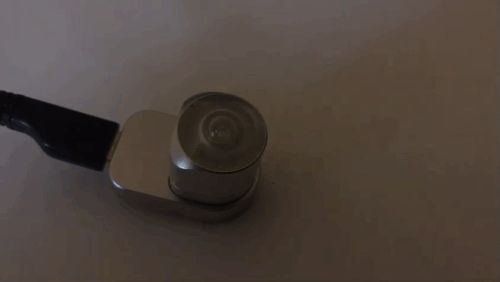
In order to connect your Antilatency Tracker with your OculusGo, you need a microUSB/microUSB cable (see part one of this tutorial for the Amazon link), and attach the tracker in the bootm center of your HDM:

Start the Antilatency apk

  1. Put your OculusGo on.
  2. From your dashboard, go to Unknown sources: you should see your apk listed. Click on it and.. you’re ready to experiment 6DOF with your OculusGo!

Here it is a final test: you can see the OculusGo moving on the floor (even outside the floor, if you look back to the floor) and the live recording of the scene.

13 Jul 2019 Posted by: Comments: 0 In: tutorial

This post will guide you through a complete Antilatency Devkit setup. We’ll follow https://antilatency.com/getting-started guide as a reference, adding some tips that will help you to get started as quick as possible. I’m assuming you have standard Devkit content:

  • 1 Antilatency tracker
  • 1 Wired USB socket
  • Tracking area equipment: 4 reference bars with markers / bar connectors / 1 power supply / floor mats

For the OculusGo part, you’ll also need a MicroUSB male -male cable, not included in the devkit (http://bit.ly/MicroUSB_IThttp://bit.ly/MicroUSB_COM)

Unity Setup

First of all, since we are going to test our devkit with Unity, we need to setup Unity in the right way. For this tutorial, I used Unity 2019.1.x with this setup:

  1. From Unity Hub, download Unity 2019.1.x version (the version number should have one letter “f” inside)
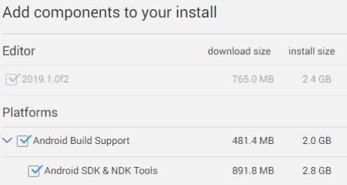
  2. Install also the Android build components:

    Once installed the right version with the right components, let’s first test our devkit inside Unity editor in desktop mode. Later, in the second part of this tutorial, we’ll see how to setup Unity to work in VR mode, allowing us to deploy our app on the OculusGo.
  3. Ensure that your build Platform is set to PC/Windows, and continue with the tutorial

Bars and floor setup

Follow the instructions at https://antilatency.com/getting-started, “Tracking area setup”. Notice that:

  • The entire setup could be easier if you first place the floormats on the floor, then connect the bars above the floor, and finally overturn the floor mats.
  • The bars orientation is taken into account, so pay attention to the Antilatency bars layout reference.
  • You need to setup the Entire Devkit floor area in order to test your Devkit correctly with OculusGo (16 floor mats, 4×4)

Once completed, your floor should look similar to this:

Software setup

In order to test your Antilatency tracker, follow the instructions at https://antilatency.com/getting-started, “Software setup/Instructions for Windows”. Notice that you have to:

  1. Run the AltSystem app
  2. Set the Environment/devkit as default layout

This step is mandatory, because when Antilatency Unity demo project will start, Antilatency API will query AltSystem to know what kind of environment layout the tracker should work with.
After this step, we are ready to test the tracker inside Unity editor. Skip the “official” Antilatency instructions steps until https://antilatency.com/getting-started, “Download SDK”

Download the SDK

  1. Download the zip file from “https://antilatency.com/getting-started”, “Download SDK”.
  2. Import Unity/AntilatencyIntegration.unitypackage inside your Unity project

Test your tracker

  1. Put your tracker into the socket and connect the socket with a standard microUSB-USB cable to your PC. The tracker should begin to blink:
  2. Open Antilatency/Integration/Samples/AltSample scene
  3. Press Play in the Unity editor
  4. Now try to move your tracker over the Tracking Area. The expected result should be:
    • As soon as  your tracker recognize 2 or more bars, it will start tracking the area correctly: in your Unity GameView you should see a Virtual environment with 4 tracking bars on the floor, correctly oriented.
    • If you come close to one bar, the tracker camera inside your Unity GameView should change its height: here we are! 6DOF tracking in your hands, thanks to Antilatency hardware!

If your tracker doesn’t recognise the scene, try to:

  • Close Unity, unplug/plug yout tracker USB cable to your PC, then start Unity again
  • Change your USB cable


Well done! This is the end of the simplest part: just a quick test to see if your Antilatency tracker is properly working. In the next part of the tutorial we’ll see how to setup Unity to deploy on OculusGo, and how to run Antilatency sample project on you OculusGo!


21 Jun 2016 Posted by: Comments: 0 In: tutorial

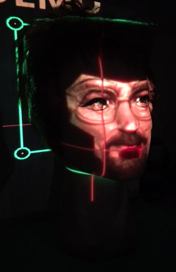
This is a simple Projection Mapping tutorial for beginners. You will use a Processing sketch to map your face (or an image file face) onto a mannequin face. The Processing sketch will record your face through your webcam or will read an image file from your disk; its output is then passed via Spout (Syphon) to the mapping software MAPIO, and then you will use MAPIO warping features to map your face onto a mannequin face using a projector.. or without it 🙂 Most of the images in this tutorial are from Windows, but the workflow for Mac users is almost the same, so you can follow it without problems.

MAPIO is a simple yet powerful Projection mapping software, that I found to be very useful especially for beginners, just to get a feel with the basic principles of projection mapping.

Spout (on Windows) and Syphon (os OSX) are two useful utilities that allows applications to share frames, video or stills, in realtime. Using these utilities, you can gather two or more video source from different software and mix, merge, edit the result using another software.


Download the software

Install Video, Spout / Syphon Libraries for Processing

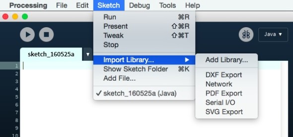
  1. In order to use our webcam with Processing, we need to install the correct library. To do so, go to: Sketch -> Import a library -> AddLibrary… (you can do this even if you don’t have a webcam)

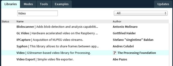
    and type in the Video in the ‘Find’ field. Click on the Video library from Processing foundation:
    Screen Shot 2016-05-25 at 17.30.51
    Click ‘Install’ button and wait for the download. If the installation will success, you should see a green circle at the beginning of the row.
  2. Windows Users: just repeat step 1, but this time installing Spout library.
    Screen Shot 2016-05-25 at 17.31.36
  3. OSX Users: just repeat step 1, but this time installing Syphon library.
    Screen Shot 2016-05-25 at 17.46.17

Run the Processing sketch

  1. Download here (WIN / OSX) the Processing sketch for the exercise.
  2. Run the Processing sketch. Use 1, 2, 3 keys to switch between 3 modes:
    1. A men faces selection
    2. A women faces selection
    3. The livestream from the webcam (if there is a webcam). Press spacebar to freeze the video-stream. It will facilitate the mapping of your static face.
  3. From now on, the Processing sketch will stream via Spout (Syphon) its output to every Spout (Syphon) receivers. We’ll use MAPIO Spout(Syphon) Built-in plugin to catch this video stream and map it onto our mannequin face.
  4. Open MAPIO.
  5. Windows users: Select Source -> Spout2 -> pmtest.
    OSX users: Select Source -> Syphon -> Processing syphon
    You should see the Processing sketch output into the Canvas area!
    2016-06-21 01_31_11-MAPIO 2 Lite (64 bits) [DEMO] - new

Let’s map your face!

  1. If you have a projector, connect it to your PC/Mac now. The second video output of your PC/Mac will be connected to our projector.
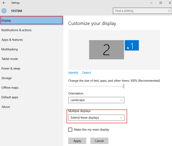
    Windows users: in your windows Settings, set the Display mode to Extend these displays.
    2016-06-21 18_39_31-Settings
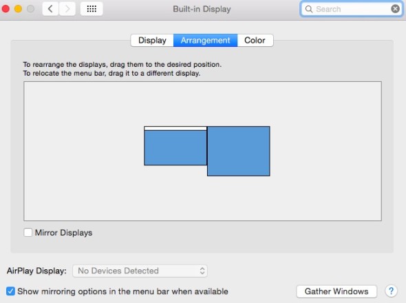
    OSX users: just open System Preferences -> Displays -> Arrangment, and make sure Mirror displays options is not checked.
    Screen Shot 2016-06-22 at 12.21.16
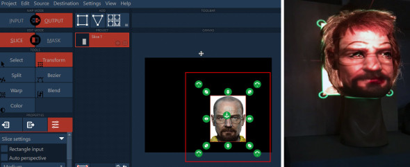
  2. Select INPUT in the Map Mode Tab (1), make sure SLICE Edit Mode is selected, and select the Transform tool from the Tools Tab (2). Now resize and move the selection around your favourite face (3).
    2016-06-21 01_35_34-MAPIO 2 Lite (64 bits) [DEMO] - new
  3. In this way we are telling MAPIO that we are only interested in that area of the input signal.
  4. If you have a Projector, then continue to the next step. If you don’t, jump at the end of the tutorial to correctly setup MAPIO, then you will return to the step 6 of this tutorial!
  5. Switch to OUTPUT Map Mode (1), choose the Display option in the Destination Menu (2). A separate window will appear (3): this is the content we will project with our projector onto our mannequin. Drag the Display Window (3) to the second screen, and double click into it to switch in full screen mode. At this point you should see your MAPIO interface in the first screen, and a fullscreen face projected from your projector.
    2016-06-21 18_34_27-MAPIO 2 Lite (64 bits) [DEMO] - new
  6. Resize the rectangle in the CANVAS tab and translate it in the canvas area: try to match the mannequin face area as close as possible (focus on the eyes and the mouth).
    pm20
  7. Now the fun part. As you noticed, there are part of your projected image that have to be replaced, to match the mannequin shape. MAPIO allows you to warp the projected in more ways. Here you can find a comprehensive video with all the MAPIO warping features. In our tutorial, we’ll focus on the Elast Mode tool. To start with it, Select the Warp tool (1), make sure you select at least Medium subdivisions in your slice settings (2), and choose Elast Mode – Elast Rect in the Toolbar (3). You should see a red rectangle on your face. Now we need to modify the The Elast Rect area: every vertex we will move will affect all the vertices in this Elast Rect area. Let’s start with the eyes: as you notice from the projection, to fill the whole mannequin face we resized our projected face, but now the glasses are too wide, we need to shrink the area between the projected eyes, mantaining (as long as possible) the position of the ears. To move on the right the left side of the glasses without create a strong distortion on the near vertices, we can influence the whole left side of the projected image: click and drag with the left mouse button from the upper left (4) to the bottom right (5) of the left side of the image.
    2016-06-21 22_19_32-MAPIO 2 Lite (64 bits) [DEMO] - new
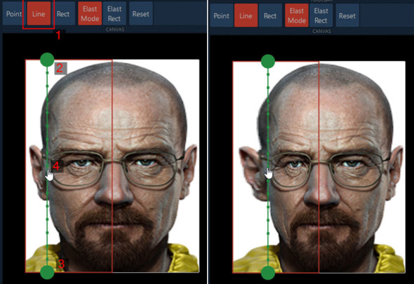
  8. Inside this area, we choose to push the glasses toward the center, starting from the left. Switch to the Line Tool (1), Click and drag from point (2) to point (3), and then click on the line you just created, and drag it to the right, until the left lens glasses will be centered on the left mannequin eye. Please note that in this tutorial we will focus on the eyes, the nose and the mouth, so we don’t care if the rest of the projected face will be distorted: we will mask it at the end 🙂
    pm22
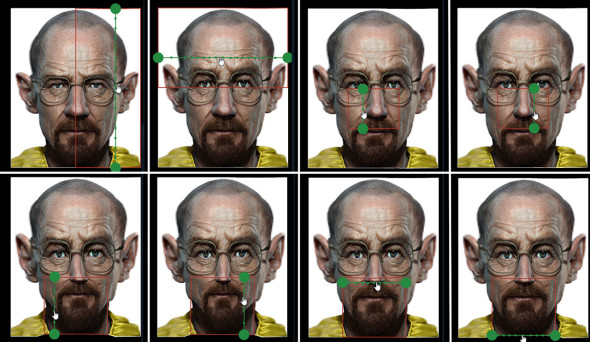
  9. Repeat the process for the right eye, the nose, and the mouth. Remember: each time you are moving a different area, you have to specify a different Elast Rect area.
    1. For the nose, use two vertical lines to adjust the left side and the right side, while mantaining the same Elast Rect area.
    2. For the mouth, use two vertical lines to adjust the left side and the right side, and two horizontal lines to adjust the beginning and the end of the beard, while mantaining the same Elast Rect area.
      pm23
  10. And here it is our result for now:
    IMG_9110
    We can turn off the areas outside the center, in this way we will also cut off the high projected distortion on the forehead, the ears and the cheeks. Le’s mask them!
  11. Click on Mask Mode (1), choose Vector Tool (2) and then click on the (+) Toolbar icon (3). Left click a few times to create a polyline around eyes, nose and mouth (4-13), double click to close the path (14), then click on Invert in the Mask properties (15).
    2016-06-21 22_55_35-MAPIO 2 Lite (64 bits) [DEMO] - new
    We obtain this:
    IMG_9112
  12. This is only a tutorial: in a real project we probably will mask the projected image with an alpha image and smoothed borders, to better merge our projected face with the mannequin one, and we will use a lot of other tricks to get a better result. Keeping things simple, we can still adjust a bit the projection. Since the mannequin has its own colour (pink), it is best to desaturate our projected image. Click on Color Tool, and set the Saturation value to 0.
    2016-06-21 23_09_05-MAPIO 2 Lite (64 bits) [DEMO] - new
  13. If you are simulating the projector, probably at this time you already get a good result. If you are using a real projector, probably you want to light up a bit the rest of the mannequin face. To do that, we can add a white background surface to the projection. Click on the Square icon in the Add Tab: a “Slide 2” rectangle will appear in the Project Tab. Drag it under the “Slice 1” rectangle.
    2016-06-21 23_10_16-MAPIO 2 Lite (64 bits) [DEMO] - new
  14. Choose Source->Image and select a white image from your disk.
    2016-06-21 23_12_15-MAPIO 2 Lite (64 bits) [DEMO] - new
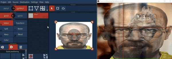
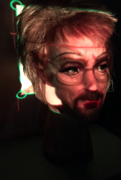
  15. Click on Color Tool (like in step 11) and adjust the Brightness until you get a good uniform (almost) result between the projected face and the projected backgroud. On the right you can see the simulated-projection result (using the Processing sketch).
    pm24

…Enjoy your result!:)

Let’s map your face (without a projector)!

Ok, so.. it turns out that your projector is broken, you lent it to your best friend a year ago, or.. you simply don’t have one, but you want to start practice with the projection mapping tools. We can simulate the projector output using for the second time the Spout (Syphon) framework, this time as a destination.

  1. Windows users: select Destination -> Spout2 from the Menu
    OSX users: select Destination -> Syphon from  the Menu
    2016-06-21 23_56_05-MAPIO 2 Lite (64 bits) [DEMO] - projector_00.mio [ ~_Documents_Projects_Projecti
  2. Select Destination -> Output settings, click on 640×480 resolution link, and click Save.
    2016-06-22 00_17_50-MAPIO 2 Lite (64 bits) [DEMO] - projector_00.mio [ ~_Documents_Projects_Projecti
  3. Download here the processing receiver sketch (WIN / OSX), open and run it.
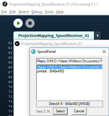
  4. Windows users: right click on the Processing output window: it will appear a menu with all the Spout senders. pmtest is our Processing sketch sender, that we are using to stream the Processing output to MAPIO. Here we need to get the MAPIO output, so choose Mapio as Spout source. Click Save.
    2016-06-22 00_33_48-SpoutPanel
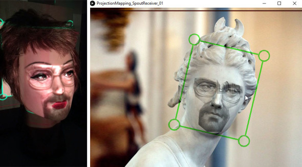
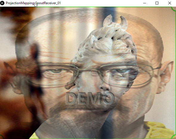
  5. Use the keys 1,2,3,4 to choose the best background onto wich you want to project your face. This background images will let you to simulate a real situation, but since you don’t have a real projector, let’s simulate a projection adding the MAPIO output to our fake background statues. You should see something like this:
    2016-06-22 01_09_28-ProjectionMapping_SpoutReceiver_01
    Our projected face is clearly too big for the background statue face, but we will adjust it soon. Now jump back to the previous tutorial steps, to number 6. Remember that every time you will see a projected image onto the mannequin face you have to imagine that face projected onto the background statue of the Processing Sketch. I know, it is not the same, but.. it is still something! Enjoy!


25 May 2016 Posted by: Comments: 0 In: tutorial

This is a simple Projection Mapping tutorial for beginners. You will use a Processing sketch to map your face (or an image file face) onto a mannequin face. The Processing sketch will record your face through your webcam, or will read an image file from your disk. The Processing Sketch output is then passed via Syphon (or Spout) to the VJ software Resolume Arena, and then you will use Resolume worping features to map your face onto the mannequin.

Download the software

Separate files

Install Video Library for Processing (OSX & Windows users)

In order to use our webcam with Processing, we need to install the correct library. To do so, go to:

Sketch > Import a library > AddLibrary...

Screen Shot 2016-05-25 at 17.30.18
and type Video in the ‘Find’ field. Click on the Video library from Processing foundation:
Screen Shot 2016-05-25 at 17.30.51
Click ‘Install’ button and wait for the download. If the installation will success, you should see a green circle at the beginning of the row.

Install SPOUT (Windows users)

We need to install SPOUT service both for Resolume and for Processing.

  • To install SPOUT for Resolume, just copy .dll files from
    C:\ProgramFiles(x86)\SpoutX\FFGL

    to

    C:\Program Files (x86)\Resolume Arena X\plugins\vfxDownload Spout
  • For Processing, we need to install the Spout library. Just Repeat the step you did to install the Video library, but this time installing ‘Spout’ library
    Screen Shot 2016-05-25 at 17.31.36

Install SYPHON (OSX users)

We need to install Syphon both for Resolume and for Processing.

  • To install Syphon for Resolume, […]
  • For Processing, we need to install the Syphon library. Just Repeat the step you did to install the Video library, but this time we will search for the ‘Syphon’ library
    Screen Shot 2016-05-25 at 17.46.17

Run the Processing sketch

  1. Download here (WIN, MAC) the processing sketch for the exercise. You need to have a connected webcam and a projector to follow the entire exercise.
  2. Run the sketch. Use 1, 2, 3 keys to switch between 3 modes:
    1. A men faces selection
    2. A women faces selection
    3. The livestream from the webcam. Press spacebar to freeze the stream. It will facilitate the mapping of your static face.
  3. From now on, the Processing sketch will stream via Spout (Syphon) its output to every Spout (Syphon) receivers. We’ll use Resolume Arena Spout (Syphon) receiver plugin to catch this stream and map it onto our mannequins.
  4. Open Resolume.
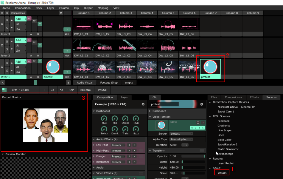
    1. Under The tab Sources you should see a Spout (Syphon) branch: it is the output of our Processing sketch. Drag and drop the pmtest (It might have a different name from this example) label from the Source tab into one of the empty console boxes (2).
    2. Click on the pmtest console box you just created: you should see the Processing sketch output into the Output Monitor area (3)!
      dragDrop

Let’s map your face!

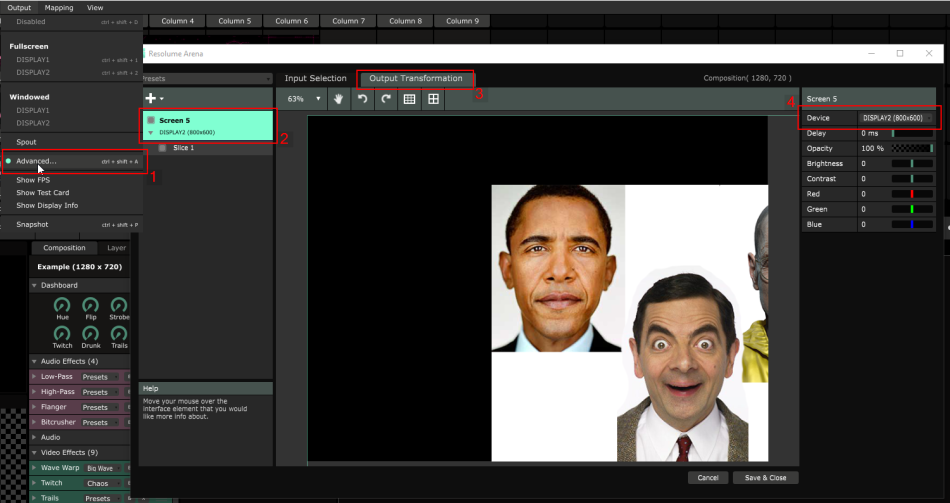
  1. Open the Advanced Output Menu from the menu Output/Advanced (1).
  2. Make sure The Screen Label (2) and the Output Transformation tab (3) are selected. In the Device Menu (4), choose the display of your projector. After that, you should see the Output Transformation tab content projected by your projector.
    2016-06-08 01_06_34-Resolume Arena - Example (1280 x 720)
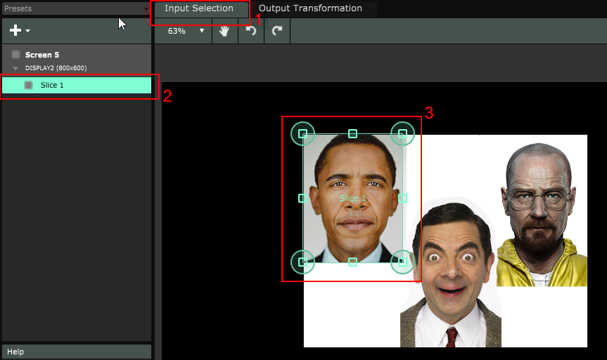
  3. Since we want to project only one face, there is no need to project the whole source processing composition onto our mannequin. Let’s select only a cropped area. Select the Input Selection tab (1) and make sure the Slice 1 label is selected (2). Now drag and drop the four corners of the highlighted area around the face you want to project (3). Now we have
    2016-06-08 01_14_04-Resolume Arena
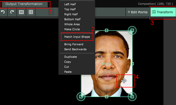
  4. Back to the Output Transformation tab (1), richgt click on the image and select Match Input Shape (2). Now that we have a more proportioned figure, Select the Transform tool (3) and drag the figure in place, to roughly match the mannequin face.
    2016-06-08 01_22_22-Resolume Arena
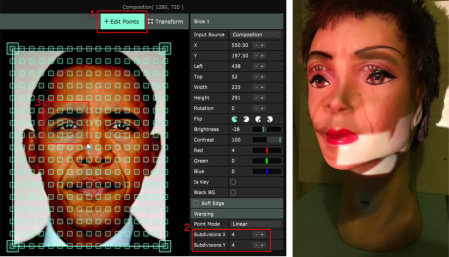
  5. Now the fun part. Choose The Edit Point tool (1) and start to subdivide the figure surface adding some movable vertices: click on ‘+’ Subdivisions X/Y until you are satisfied. These vertices added to our figure allows us to move only specific portion of the face texture, to refine the mapping and warp the image to perfectly align the face in the figure to the mannequin one. For example, if you want to move the entire right eye, you should select the area highlighted with the number (3) (by dragging the left mouse button). Once the vertices are selected, you can move them altogether.
    2016-06-08 01_54_19-Untitled-1 @ 50,1% (File_000, RGB_8) _
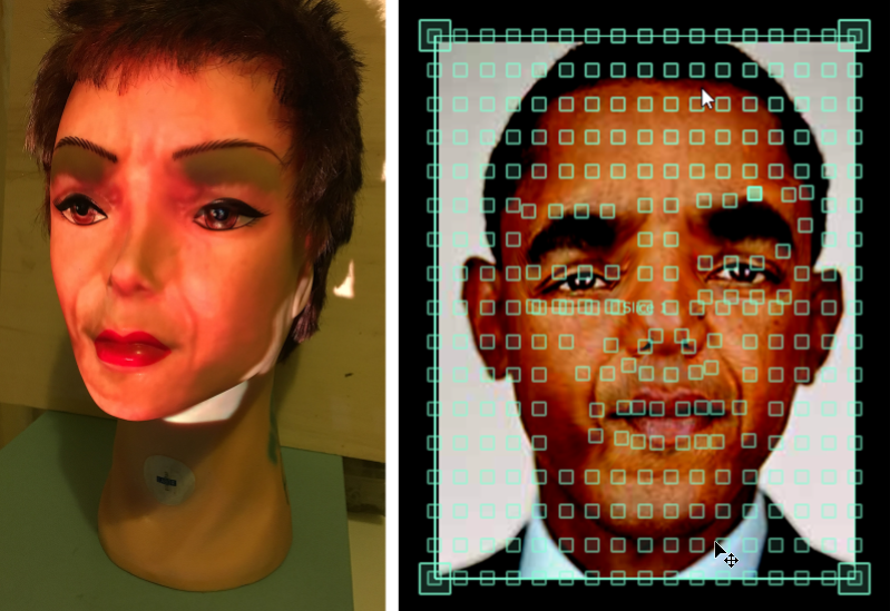
  6. Repeat the previous step until you get the desired result. In the following images you can see the final result (still very rough, no time to map 🙂 and the resulting warped image.
    2016-06-08 01_54_52-Untitled-1 @ 50,1% (2016-06-08 01_39_27-Resolume Arena, RGB_8) _
14 Jun 2014 Posted by: Comments: 0 In: tutorial

Lately I have received many requests on how to use iniTree and iniSphere in VDMX. Below you will find a simple guide on how to do that. I’ll show how to use iniTree patch, but the same steps apply also to iniSphere and other patches! Hope it helps!

NB: use only 32bit version of inimart plugins if you want to use them with VDMX or CoGe. 64bit version is not supported yet!!!

Each Quartz Composer patch can have as many published VDMX inputs as needed: instead of simply use right click + publish input on the patch, we need to use input splitters. Here it is how:

  1. Insert iniTree patch in your composition.
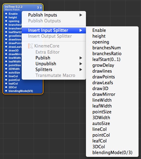
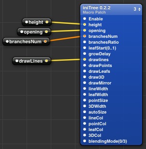
  2. Right click on iniTree patch -> insert input splitter -> choose for the input you want to publish into VDMX/CoGe. We’ll go for Height, Opening, Branches Num and DrawLines for this example.Screen Shot 2014-06-14 at 15.19.08
  3. Right click on Height input splitter -> publish input -> input. Choose a right name for this input (hum.. Height, for example? 🙂 ). Do the same for the other input splitters.Screen Shot 2014-06-14 at 16.44.42
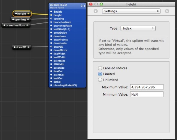
  4. Now you need to tell VDMX witch kind of value you will accept for this input. Click on Height input splitter, and open the Setting parameters by pressing ⌘2 (cmd + 2) on the keyboard.
  5. The Type setting will set the input type. The type names you’ll find here are quite self-explanatory, only one note on the difference between Index and Number:
    • Index is the same of Whole type in math: from 0 to N, without decimals. You can specify a sequence of labels associated with indices values (a sort of enum, if you know a bit programming stuff);
    • Number is the same of Real type in math (float in programming): from -N to N, with decimals.Screen Shot 2014-06-14 at 15.42.56
  6. Taking into account iniTree free limitations on tree rendering, Choose this settings for input splitters:
    • Height – Type: Index / Limited / Maximum Value: 4 / Minimum Value: 0
    • Opening – Type: Number / Limited / Maximum Value: 10 / Minimum Value: 0
    • Branches Num – Type: Index / Limited / Maximum Value: 4 / Minimum Value: 0 (This input can be also a Number with the same range, if you want to use intermediate Branches angles).
    • DrawLines – Type: Boolean
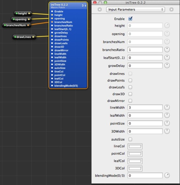
  7. Setup the other iniTree input to let VDMX/CoGe render something also if you’ll use only the 4 input splitter inputs.
    • BranchesRatio: 1
    • GrowDelay: 10
    • LineWidth: 3Screen Shot 2014-06-14 at 16.15.57
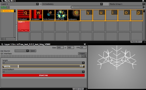
  8. That’s it! Save the composition, open VDMX/CoGe, and drag the composition in one free slot. The input splitter value types will be read, and will provide you an input panel for your Quartz Composer animations!Screen Shot 2014-06-14 at 16.39.18
    CoGeTest

You can download the example composition for this tutorial (using iniTree plugin) here:

[wpdm_file id=11]

27 Dec 2013 Posted by: Comments: 1 In: tutorial

Here you can download a simple Quartz Composer composition to show how you can link iniSphere input (but the same approach is valid for all the other plugin) to audio output, to create audioreactive compositions.

audioReactive_00

Very simple, but someone novice might find it interesting. 🙂

To run it, you need to install:

Download from here:

[wpdm_file id=10]